Kit includes the following;
- Qty. 1 – Paper Lantern
- Qty. 1 – AA Battery Pack
- Qty. 1 – LED Strip with 30 digitally controllable RGB LEDs
- Qty. 1 – Pink bag with electronic parts for the Bantam Board LED controller
Tools and extras you will need;
- Soldering iron with solder.
- Micro flush cutters.
- Wire stripper for 24awg wire.
- Quilt batting – you can buy this from most craft stores.
- Hot glue gun.
- Qty. 3 AA batteries.
Assemble the electronics:

The pink bag contains the following parts needed to assemble the Bantam Board that will be used to control the LED strip.
- Qty. 1 – Bantam Board PCB
- Qty. 1 – 28 Pin Socket
- Qty. 1 – Atmega 328P – 28 Pin microcontroller
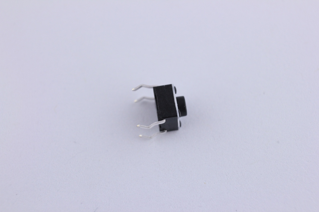
- Qty. 1 – Push button
- Qty. 1 – 16 MHz crystal
- Qty. 2 – .1µF ceramic capacitors – indicated with “104”
- Qty. 2 – 10pF ceramic capacitors – indicated with “100”
- Qty. 1 – 10KΩ resistor – stripe colors -brown, black, orange
- Qty. 1 470Ω resistor – stripe colors – yellow, purple, brown
- Qty. 1 – 6 pin header
- Qty. 1 – 2pin – JST plug (for use with lithium polymer battery)
Start with the bare PCB shown below.

Step 1: Solder the two .1µF ceramic capacitors – indicated with “104” into “C1” and “C2”. They are non-polarized capacitors so they can be placed in either direction.

Step 2: Solder the two 10pF ceramic capacitors – indicated with “100” into “C3” and “C4”. They are non-polarized capacitors so they can be placed in either direction.

Step 3: Solder the 16 MHz crystal into “Q1”. This part is also non-polarized.

Step 4: Solder the 10KΩ resistor into “R1”. You will need to bend the wire leads on both ends.

Step 5: Solder the 470Ω resistor into “R2”.

Step 6: Solder the push button switch into “S1”. This switch can be placed into the holes in either direction.

Step 7: Solder the 28pin socket into “U1”. The socket has a notch on on end and should be placed as indicated on the PCB with the notch facing left.

Step 8: Insert the 28pin microcontroller into the socket. The notch on the microcontroller needs to be in the same direction as the socket above. Facing to the left. The green dot is also on the same side as the notch. You may need to use your fingers to pinch the pins on the microcontroller closer in order to fit into the socket.

Step 9: (Optional) Solder the 6pin header into the holes labeled, GND,CTS,5V,TX,RX,DTR. The shorter side goes into the PCB. This is only needed if you plan to re-program your Bantam Board with different colors and patterns. 
Step 10: Solder the wires from the AA batter pack. Red wire goes to the positive side “+” and Black wire goes to the negative side “-“. If you plan to use a lithium polymer batter pack instead, use the 2pin JST plug.

Step 11: Solder the wires from the LED strip. The LED light strip has indication arrows. We will be using the end where the arrows are pointing away from the red/green/white wires. You will need to cut the plug off of the end and strip the wires. There are two additional red and white wires. These are not needed. Make sure you cut any bare wires to make sure they don’t touch and short out. The PCB has holes marked RED, GRN, WHT.


That’s it for the electronics assembly. You will end up with this shown below.

Make the “Cloud”
Step 1: Assemble the paper lantern by expanding it and using the metal wire frame to keep its structure.

Step 2: Glue the batting to the lantern using a hot glue gun. Pull the batting apart into chunks. Pull the chunk apart a few times to give it extra fluff. The more random they look the better it will turn out. Use a hot glue gun and put glue onto the lantern first then press the fluffy chunk into the glue. Hold it there for a few seconds to let the glue dry. Repeat this until the entire lantern is fully covered. Keep the top clear in order to place the electronics inside.

Step 3: Place the electronics inside the lantern. try to coil and string the LED strip around inside the get the best light coverage.

Step 4: Hang it up and turn it on! Don’t forget to place 3 AA batteries in the battery pack. We used fishing line and tied it to the metal frame. We will be updating the code to add other lighting effects. Check back soon for more details on how to reprogram it for other cool colors and patterns.
